In high-precision manufacturing, “close enough” is never enough. Whether you are developing surgical implants, aerospace flanges, or automotive transmission components, the functionality and assembly of your parts depend entirely on dimensional accuracy.
In Computer Numerical Control (CNC) machining, precision and tolerance dictate the allowable variation in a part’s physical dimensions. Setting the correct tolerances ensures that components fit together perfectly in complex mechanical assemblies while preventing unnecessary manufacturing expenses.
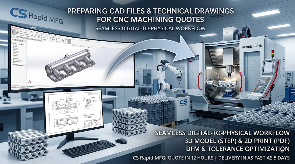
This guide explores what CNC machining tolerances mean, compares general versus tight tolerances, examines key factors affecting machining precision, introduces Geometric Dimensioning and Tolerancing (GD&T), and explains how CS Rapid MFG guarantees uncompromised quality control.
What Are CNC Machining Tolerances?
A tolerance is the acceptable range of variation for a specific dimension defined in an engineering drawing. Because no manufacturing machine can cut material to a mathematically perfect dimension every single time, engineers assign tolerance limits (such as ±0.005 in or ±0.10 mm) to ensure functional reliability.
For example, if a shaft’s nominal diameter is specified as 10.00 mm with a tolerance of ±0.05 mm, any finished shaft measuring between 9.95 mm and 10.05 mm is deemed acceptable and functional.
General vs. Tight Tolerances: Striking the Right Balance
When specifying dimensions on your 2D engineering drawings or 3D CAD models, tolerances generally fall into two categories:
1. General Tolerances (Standard Machining)
General tolerances represent a machine shop’s standard capability for features where high precision is not strictly required.
- Standard Values: In precision CNC turning and milling, standard general tolerances typically range around ±0.005 in (±0.13 mm) or ±0.10 mm.
- Best Used For: Non-mating outer surfaces, general mounting brackets, clearance holes, and decorative housings.
- Benefit: Provides an optimal balance between high manufacturing speed, low tool wear, and cost efficiency.
2. Tight Tolerances (High-Precision Machining)
Tight tolerances require specialized tooling, slower cutting speeds, temperature-controlled machining environments, and 100% metrology inspection.
- Standard Values: Tighter tolerances can reach ±0.001 in (±0.025 mm), down to ±0.005 mm (±0.0002 in) upon engineering review.
- Best Used For: Bearing seats, internal valve spools, press-fit pins, aerospace flanges, and optical lens tubes.
To understand how over-specifying tight tolerances inflates production costs, read our complete Guide to Design for Manufacturability in CNC Turning.
Key Factors That Impact CNC Machining Precision
Achieving micro-meter precision requires managing multiple physical and mechanical variables during the machining process:
- Machine Capability and Axis Alignment: Multi-axis CNC machines (such as 5-axis Hermle or DUG milling centers and Swiss-type lathes) complete complex features in a single setup, eliminating setup errors and preserving reference zeroes.
- Material Thermal Expansion and Elasticity: Metals and plastics respond differently to cutting heat and clamping force. Metals expand under high cutting temperatures, while flexible plastics deform under chuck pressure.
Explore how metal thermal conductivity impacts machining stability in our Guide to Selecting the Best Metals for CNC Machining.
Learn how to avoid part deformation when machining polymers in our Feature on Engineering Plastics for CNC Turning.
Tool Wear and Cutting Pressure: As cutting inserts wear down, tool geometry changes slightly, which can alter final dimensions if uncompensated by automated machine probing.
Ambient Temperature Control: At extreme precision levels (below ±0.01 mm), room temperature changes cause raw metal stock to expand or contract. High-precision inspection must take place in climate-controlled quality labs.
Geometric Dimensioning and Tolerancing (GD&T)
- Standard linear tolerances control distance, diameter, and length. However, complex engineering components often require control over geometric shape and orientation. GD&T (Geometric Dimensioning and Tolerancing) uses a standardized system of symbols to define feature relationship limits:
- Flatness: Ensures a planar surface does not bow or wave (critical for sealing flanges).
- Concentricity & Cylindricity: Ensures cylindrical turned shafts rotate on a true central axis without wobble.
- Perpendicularity & Parallelism: Controls the exact 90-degree alignment or parallel spacing between mating faces.
- Runout: Measures variations when a turned part is rotated along its central axis, essential for high-speed dynamic shafts.
Applying GD&T symbols on 2D technical drawings gives machinists clear targets for critical functional surfaces while keeping non-critical areas at standard tolerances.
How CS Rapid MFG Guarantees Precision and Accuracy
When manufacturing high-precision prototypes or production runs, having a certified quality assurance process is vital. CS Rapid MFG bridges advanced subtractive technology with rigorous metrology verification.
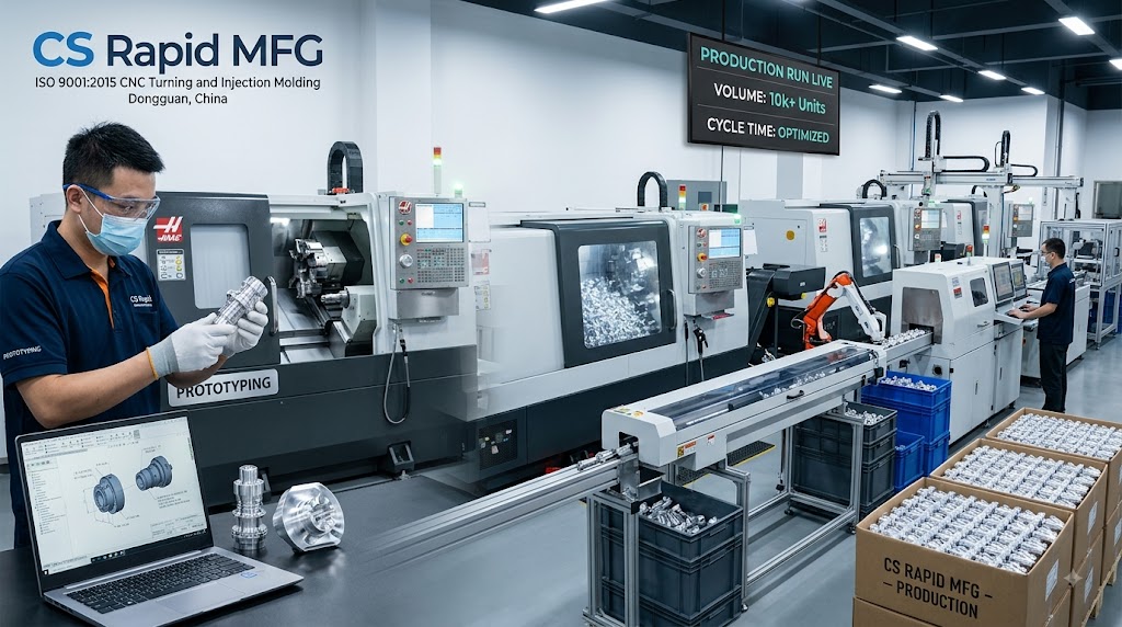
Located in Dongguan, China, our manufacturing facility operates under strict global quality systems and is proudly ISO 9001:2015 certified. We house over 80 high-precision 3-axis, 4-axis, and Hermle/DUG 5-axis CNC machines along with multi-axis live tooling lathes.
Read The Ultimate Guide to CNC Machining to discover how our multi-axis manufacturing capabilities take your parts from prototype to mass production.
Our Rigorous Quality Control Process:
- Preliminary DFM Review: Upon receiving your inquiry, our engineering team evaluates your tolerances, GD&T callouts, and dimensions within 12 hours to catch manufacturability issues before production begins.
- In-Process Inspection: Project engineers conduct ongoing dimensional checks during manufacturing runs to verify tolerance stability.
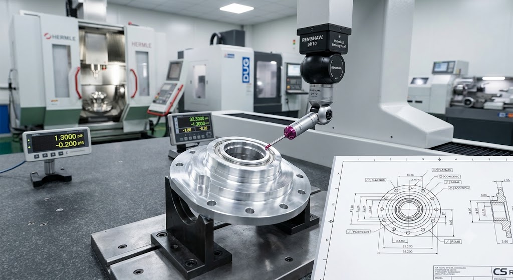
- Advanced Metrology Equipment: Our quality assurance lab utilizes Coordinate Measuring Machines (CMM), optical profile projectors, and digital height gauges to perform 100% CMM inspection for high-requirement components.
- Fast Lead Times with No MOQ: We manufacture tight-tolerance custom parts in as fast as 5 days with No Minimum Order Quantity (MOQ) required.
Ready to verify your tolerances and manufacture high-precision custom parts? Contact CS Rapid MFG today or upload your 2D and 3D files for an instant quote within 12 hours.