| Symbol |
Modifier |
Notes |
 |
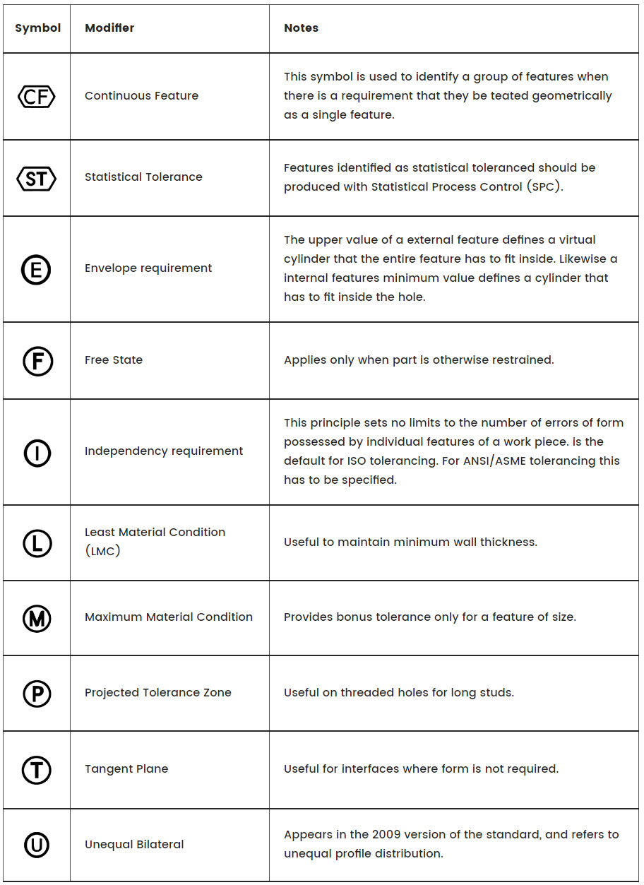
Continuous Feature |
This symbol is used to identify a group of features when there is a requirement that they be teated geometrically as a single feature. |
 |
Statistical Tolerance |
Features identified as statistical toleranced should be produced with Statistical Process Control (SPC). |
 |
Envelope requirement |
The upper value of a external feature defines a virtual cylinder that the entire feature has to fit inside. Likewise a internal features minimum value defines a cylinder that has to fit inside the hole. |
 |
Free State |
Applies only when part is otherwise restrained. |
 |
Independency requirement |
This principle sets no limits to the number of errors of form possessed by individual features of a work piece. is the default for ISO tolerancing.
For ANSI/ASME tolerancing this has to be specified. |
 |
Least Material Condition (LMC) |
Useful to maintain minimum wall thickness. |
 |
Maximum Material Condition |
Provides bonus tolerance only for a feature of size. |
 |
Projected Tolerance Zone |
Useful on threaded holes for long studs. |
 |
Tangent Plane |
Useful for interfaces where form is not required. |
 |
Unequal Bilateral |
Appears in the 2009 version of the standard, and refers to unequal profile distribution. |