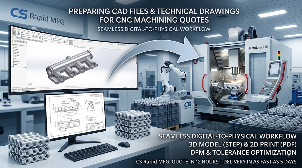
In subtractive manufacturing, product cost is largely determined long before a cutting tool touches the raw material. While choice of equipment and shop capabilities play significant roles, decisions made on the CAD drawing board—such as feature geometry, dimensional tolerances, and material allocation—account for up to 80% of total manufacturing costs.
Design for Manufacturability (DFM) is the engineering practice of designing components so they are easy and economical to manufacture. Applying DFM principles specifically to CNC turning ensures that parts move smoothly through production with minimal tool wear, shortened machining cycles, and reduced scrap rates.
This comprehensive guide outlines the most effective DFM design rules for turned components and demonstrates how optimizing your CAD models directly translates into substantial manufacturing savings.
Match Part Dimensions to Standard Raw Bar Stock
One of the simplest ways to lower CNC turning costs is to standardize your part’s outside diameter (OD).
Raw metal and plastic materials are purchased in standard bar stock sizes (e.g., 0.5 in, 1.0 in, 25 mm). If your design specifies an OD of exactly 1.000 in, the machinist must select a larger 1.125 in bar and machine away 0.125 in of material across the entire length of the component.
DFM Recommendation:
- Design your part’s maximum outside diameter to be slightly smaller than a standard bar stock size (for example, specifying an OD of 0.980 in instead of 1.000 in).
- This approach minimizes the volume of material that needs to be cut away, saving raw material costs and reducing machine cycle time.
Control Length-to-Diameter Ratios to Prevent Deflection
During CNC lathe operations, the workpiece rotates at high speeds while being subjected to lateral pressure from the cutting tool. If a part is excessively long and thin, cutting forces cause the material to bend, vibrate, or deflect.
Deflection leads to chatter marks, out-of-spec taper errors, and potential tool breakage. While machinists can counteract deflection using steady rests or tailstocks, setting up these auxiliary supports increases manual labor and machine setup time.
DFM Recommendation:
- Aim for an optimal length-to-diameter (L/D) ratio of 2:1 or 3:1.
- For long, slender components with high L/D ratios, specialized equipment is required to maintain accuracy without deflection.
- For slender parts requiring extreme length-to-diameter ratios, explore our deep dive into Swiss-Type Lathes for long and micro parts.
Optimize Internal Geometries: Radii, Wall Thickness, and Hole Depths
Internal features like cavities, bores, and thin walls are significantly more challenging to machine on a lathe than exterior surfaces.
Avoid Sharp Internal Corners
Because cutting tools are inherently round, machining a true 90-degree sharp internal corner is physically impossible without specialized secondary operations.
Fix: Always specify an internal radius at steps and shoulders. Allowing a generous radius (e.g., R 0.5 mm or larger) allows the tool to sweep smoothly along the path at higher feed rates.
Maintain Safe Minimum Wall Thickness
Thin-walled tubular parts are vulnerable to cracking or distortion under chuck clamping pressure or cutting loads.
Fix: Maintain a minimum wall thickness of 0.020 in (0.51 mm) for metal parts. For flexible plastics, wall thicknesses should be even thicker to avoid permanent deformation.
Manage Hole Depth-to-Diameter Ratios
Drilling or boring deep internal holes requires long, slender boring bars that are prone to tool deflection.
Fix: Keep internal hole depths within 3 to 5 times the hole diameter. When the depth-to-diameter ratio exceeds 10:1, machining becomes exceptionally difficult and requires specialized tooling, driving up unit costs.
Standardize Thread Depths and Thread Classes
Threaded features are common in custom turned parts, but over-specifying thread depth is a frequent cause of tool breakage and inflated machining expenses.
Most of the mechanical holding strength of a threaded fastener is concentrated in the first 3 to 5 threads. Cutting threads deeper than necessary adds machining time without providing extra structural benefit.
DFM Guidelines for Threading:
- Small Threads (Ø 1.5 mm to 5 mm): Limit thread depth to up to 3 times the thread diameter.
- Larger Threads (Ø ≥ 5 mm): Keep thread depth between 4 to 6 times the thread diameter.
- Whenever possible, specify standard UNC/UNF or Metric thread classes rather than custom helical profiles to utilize off-the-shelf taps and threading inserts.
Avoid Over-Specifying Tolerances and Surface Finishes
- Tight tolerances (e.g., ±0.001 in / ±0.025 mm) and ultra-smooth surface finishes require slower cutting speeds, frequent tool inspections, and specialized quality control equipment.
- Applying tight tolerances across non-critical dimensions unnecessarily increases production costs.
- Learn more about defining cost-effective dimensional limits in our Guide to CNC Machining Precision and Tolerances
- Discover how post-processing affects part aesthetics and budget in our Overview of Common Surface Finishes for CNC Parts
As a rule of thumb, apply general tolerances (such as ±0.005 in / ±0.13 mm) for non-mating surfaces, and reserve tight tolerances strictly for critical bearing seats, press fits, and sealing surfaces.
Consolidate Complex Features with Live Tooling
If your turned part requires secondary features like milled flats, radial holes, keyway slots, or off-center threads, designing them specifically for single-setup machining prevents the need to transfer the workpiece to a separate milling machine.
Optimize Your Manufacturing Costs with CS Rapid MFG
Designing for manufacturability is an iterative process, and having an experienced manufacturing partner by your side ensures your CAD designs are fully optimized before production begins.
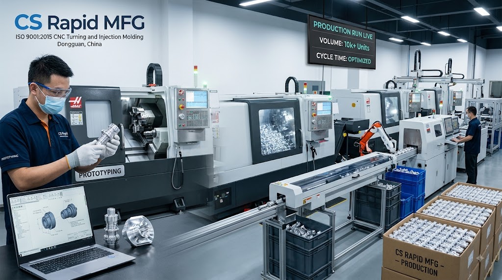
At CS Rapid MFG, we bridge the gap between design engineering and efficient manufacturing. Operating out of Dongguan, China, our ISO 9001:2015 certified facility houses over 80 high-precision CNC machines—including Hermle and DUG 5-axis mills and multi-axis live tooling turning centers.
To see how our complete manufacturing ecosystem supports your product development roadmap, read The Ultimate Guide to CNC Machining.
Why Work with CS Rapid MFG?
Free DFM Analysis: Every inquiry receives a thorough Design for Manufacturability review within 12 hours. Our engineering team evaluates your tolerances, wall thicknesses, and tool paths to identify cost-saving opportunities before cutting metal.
Rapid Delivery: We shorten development cycles, delivering completed prototypes and production components in as fast as 5 days.
Agile Flexibility: We enforce No Minimum Order Quantity (MOQ)—order 1 prototype or thousands of production parts with full engineering support.
Global Value: Enjoy high-precision manufacturing with pricing +30% lower than western competitors.
Ready to optimize your CAD designs and lower your CNC turning costs? Contact CS Rapid MFG today or upload your 2D and 3D files for an instant quote within 12 hours.