In modern digital manufacturing, the bridge between a brilliant engineering concept and a physical precision part is the digital data you submit to your manufacturing partner. Whether you are developing a rapid prototype or launching a high-volume production run, the quality and completeness of your 3D CAD files and 2D technical drawings directly dictate how quickly and accurately your project can be quoted and manufactured.
Submitting incomplete or unoptimized design files often leads to back-and-forth communication, delayed quotes, and an increased risk of manufacturing errors.
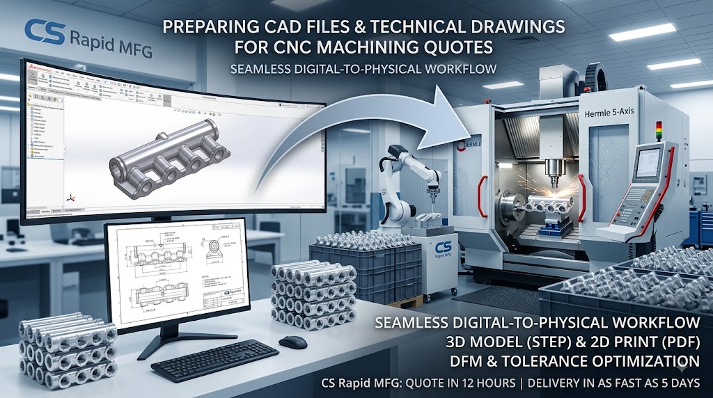
This step-by-step guide outlines how to prepare your CAD models and 2D technical drawings to secure a fast, precise quote and ensure a seamless production run.
1. Export Your 3D CAD Models into Standard Formats
The first step in preparing your manufacturing package is exporting your 3D design from your native Computer-Aided Design (CAD) software (such as SolidWorks, Autodesk Inventor, or Fusion 360) into a universally compatible file format.
While proprietary files can sometimes be read, native formats are prone to translation errors when opened in different software versions.
- The Gold Standard (STEP / .stp): STEP is the industry-standard neutral file format. It preserves three-dimensional geometric data, faces, and surfaces with extreme accuracy, making it the most reliable format for CNC programmers.
- Alternative Formats: Other highly compatible formats include IGES (.igs), SLDPRT, IPT, PRT, and SAT.
- Avoid Mesh Files (STL / .stl): While STL files are perfect for 3D printing, they represent surfaces as a mesh of triangles. This format lacks the precise mathematical curves and boundary representations needed for CNC turning and milling G-code generation.
2. Pair Your 3D Model with a 2D Technical Drawing
A common misconception is that a 3D CAD file contains all the information a machinist needs. While the 3D model defines the overall geometric shape, it cannot communicate critical manufacturing instructions.
A 2D technical drawing (usually submitted as a PDF) is a legally binding document that guides quality control and inspection. You should always include a 2D drawing if your part features:
- Tight Tolerances: If a dimension requires tighter limits than standard general tolerances, it must be explicitly labeled on the 2D drawing.
- Threaded Holes and Specifications: Specify the exact thread class, pitch, and depth (such as M6x1.0 or 1/4-20 UNC).
- Surface Finish Requirements: Indicate if specific faces require polishing, anodizing, or bead blasting.
- Geometric Dimensioning and Tolerancing (GD&T): Use standard symbols to define critical flatness, concentricity, or parallelism requirements.
- Learn more about defining cost-effective tolerances on your 2D prints in our Guide to CNC Machining Precision and Tolerances.
3. Standardize Internal Geometries and Pre-Check DFM
Before uploading your files for a quotation, performing a quick internal Design for Manufacturability (DFM) self-check can prevent design revisions later.
Machining tools are cylindrical and rotate at high speeds. Designing features that do not match tool geometries drives up cycle times and costs.
- Design Generous Fillets: Ensure all internal vertical corners have a radius. Avoid sharp 90-degree internal corners, which cannot be cut cleanly with standard rotating end mills.
- Avoid Overly Deep Cavities: Limit the depth of your milled pockets to 4 times their width to minimize tool deflection and chatter.
- Review Wall Thicknesses: Ensure metal walls are at least 0.8 mm thick, and plastic walls are at least 1.5 mm thick, to prevent deformation under cutting pressure.
- To ensure your part geometry is fully optimized to lower manufacturing costs, check our Smart DFM Design Strategies to Reduce CNC Turning Expenses.
4. Specify Materials and Post-Processing Finishes
Clearly communicate your material selection and secondary finishing requirements within your request for quote (RFQ) notes or on the 2D drawing block.
Different metals and plastics have vastly different machinability rates, which heavily impacts your final price. Similarly, secondary operations like hardcoat anodizing or electroless nickel plating require precise preparation and affect dimensional tolerances.
Secure an Instant Quote with CS Rapid MFG
Preparing your files correctly is the best way to accelerate your product development lifecycle. At CS Rapid MFG, we make the quoting and manufacturing process as smooth and transparent as possible.
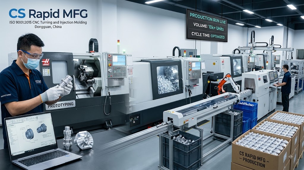
Located in Dongguan, China, our advanced facility is proudly ISO 9001:2015 certified. We operate more than 80 high-precision CNC processing machines—including Hermle and DUG 5-axis milling centers and multi-axis live tooling lathes—supported by a team of over 100 experienced technicians.
Our Seamless 4-Step Manufacturing Process:
- Get a Quote within 12 Hours: Upload your 2D and 3D CAD files (STEP, STP, SLDPRT, etc.) along with your specifications. Our team will review your project and provide a precise quotation.
- Complimentary DFM Analysis: Once your order is confirmed, our engineers will provide a detailed Design and Manufacturing analysis report, reviewing all tolerances and features to optimize part quality.
- Start Production: Upon DFM approval, we initiate CNC machining. Project engineers conduct thorough inspections of dimensions, tolerances, and appearance during manufacturing to ensure part consistency.
- Delivery in as Fast as 5 Days: Following final quality inspection, your custom parts are packaged securely and shipped directly to your location with on-time delivery guaranteed.
Ready to streamline your next hardware project? Contact CS Rapid MFG today or upload your CAD files to receive a comprehensive quote within 12 hours.