In the rapidly evolving world of subtractive manufacturing, choosing the right production method is the most critical decision an engineer or product designer can make. Computer Numerical Control (CNC) machining is an umbrella term that encompasses several distinct technologies, with CNC Milling and CNC Turning acting as the two foundational pillars.
While both processes rely on computer-generated G-code to accurately remove material from a raw block or rod, they are fundamentally different in their mechanics, tooling, and ideal applications. Understanding the nuanced differences, the specific advantages, and the inherent limitations of both turning and milling will empower you to optimize your part designs, reduce manufacturing costs, and select the perfect process for your project.
Fundamental Mechanics: How Do They Differ?
The primary distinction between CNC turning and CNC milling lies in the motion principle—specifically, the relationship between the cutting tool and the raw material.
Mechanics of CNC Milling
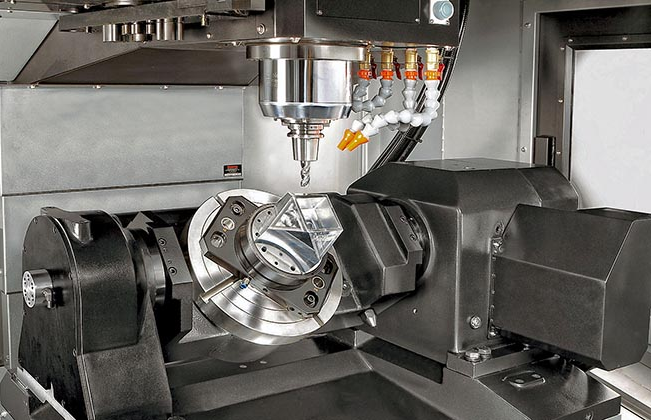
In the CNC milling process, the raw material (workpiece) is clamped securely to the machine bed and remains stationary (or moves linearly along specific axes). A high-speed cutting tool rotates around the X, Y, and Z axes to carve away material and create a three-dimensional shape.
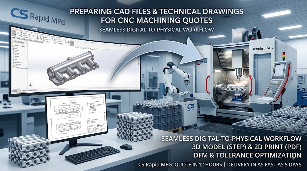
Advanced milling machines, such as the Hermle and DUG 5-axis precision milling machines utilized at CS Rapid MFG, can manipulate the tool or the bed across five distinct axes simultaneously. This allows the cutter to approach the stationary material from almost any angle.
Mechanics of CNC Turning
Conversely, CNC turning is a process by which material is cut to create round shapes using a CNC Lathe. In this setup, the workpiece is placed inside the lathe and rotates at high speeds, while a stationary single-point cutting tool is fed into the rotating material to progressively shave it away until the desired geometry remains.
To understand turning fully, it is helpful to know the anatomy of a CNC lathe:
Headstock & Spindle: The key component that supports the mechanism responsible for rotating the workpiece.
Chuck: Attached to the spindle, the chuck (usually featuring 3 or 4 jaws) grips and holds the rotating raw material bar firmly in place.
Carriage: Located between the headstock and tailstock, it guides the cutting tool linearly against the rotating workpiece.
Tailstock: When machining parts that have a length much greater than their diameter, the protruding free end of the workpiece needs support to avoid flexing and vibrating. The tailstock holds this free end securely.
Deep Dive: CNC Milling
Milling is often considered the most versatile of the CNC processes, but it comes with its own set of pros and cons.
Advantages of CNC Milling
Unmatched Geometric Complexity: Milling is the undisputed champion of complex, asymmetric, and prismatic 3D shapes. If your part resembles a block, requires deep pockets, intricate internal cavities, or flat contoured surfaces, milling is required.
Versatile Tooling: A single milling machine can hold a massive magazine of different tools (end mills, face mills, drills, taps).
Reduced Setups with 5-Axis: With 5-axis CNC machining, complex parts can often be machined in a single setup, drastically reducing handling errors and improving overall feature-to-feature tolerance alignment.
Disadvantages of CNC Milling
Slower for Cylindrical Parts: While a mill can create a circular profile using circular interpolation, it is significantly slower and less efficient than spinning the part on a lathe.
Tool Marks on Curves: When milling a round surface, the rotating tool often leaves visible “step” marks or interpolation lines, resulting in a surface finish that is generally inferior to that of a turned part.
Deep Dive: CNC Turning
Turning is highly specialized, offering incredible efficiency for the right geometries.
Advantages of CNC Turning
Supreme Speed and Economics: For parts with rotational symmetry, turning is incredibly fast. It is highly economical for both short prototype runs and long, high-volume production orders.
Exceptional Surface Finishes: Turned parts generally achieve a very smooth as-machined finish on cylindrical surfaces. The continuous cutting motion of a lathe typically produces a more uniform appearance and lower surface roughness (often reaching Ra 125 µin) compared to milled surfaces.
Automation for Mass Production: For serial production, CNC turning machines can be equipped with bar feeders. These devices automate the material handling process by feeding a continuous length of bar stock directly into the spindle, saving immense labor costs and shortening delivery times.
High Precision Concentricity: Because the part itself is spinning on a true axis, turning naturally guarantees excellent concentricity and high dimensional tolerances for outer and inner diameters (OD/ID).
Disadvantages of CNC Turning
Design Limitations: Traditional 2-axis lathes are strictly limited to symmetrical, cylindrical, or spherical shapes.
Deflection Risks (Length-to-Diameter Ratios): Lathes struggle with flimsy shapes or parts with a very high length-to-diameter ratio, as the cutting pressure can cause the material to deflect or vibrate. For example, machining deep precision holes becomes highly challenging when the depth-to-diameter ratio exceeds 10:1 without specialized tools like a boring bar, steady rest, or tailstock.
The Evolution: Blurring the Lines
Modern manufacturing technology has evolved to overcome the individual limitations of standard mills and lathes.
1. CNC Lathes with Live Tooling
Today, you are no longer restricted to purely round features on a lathe. Modern CNC turning centers feature “live tooling”—driven rotary tools mounted on the lathe’s turret. While the main workpiece is held in the chuck, these live tools can perform secondary milling operations, such as drilling axial and radial holes, tapping threads, cutting slots, and machining flats directly into the workpiece. This eliminates the need to transfer the part to a separate milling machine.
2. Swiss-Type Lathes for Micro-Machining
To combat the deflection issues of long, slender parts, the industry utilizes Swiss-type lathes. These machines are unique because the stock material is fed through a guide bushing. This allows the cutting tool to operate extremely close to the point of support, preventing the material from bending. Swiss-type lathes are incredibly cost-effective for complex, long, and micromachined turned parts.
How to Choose Between CNC Turning and Milling
When analyzing your CAD design, consider the following criteria to determine the best manufacturing route:
1. Analyse the Part Geometry
This is the most decisive factor. Look at your part’s overall shape. Does it have rotational symmetry? Common turned shapes include straight cylinders, tapered cones, threaded shafts, and parts with O-ring grooves or knurled handles. If your part is a rod, shaft, spacer, or pin, choose CNC Turning. If your part is a square block, an engine manifold, or a flat enclosure, choose CNC Milling.
2. Evaluate Production Volume
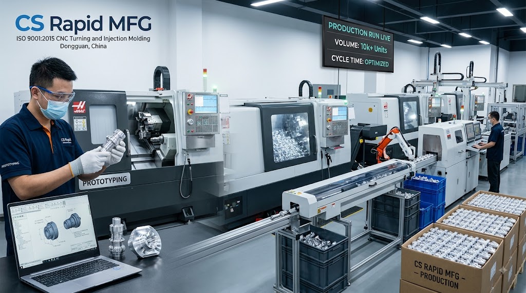
If you need 10,000 cylindrical spacers, a CNC lathe equipped with an automatic bar feeder will produce these parts continuously, with minimal human intervention, making it significantly cheaper and faster than setting up a mill.
3. Surface Finish Requirements
If the outer diameter of your part requires a pristine, smooth finish for a bearing fit or an airtight seal, turning is the superior choice. It naturally provides a smoother finish on outer and inner diameters without the need for extensive secondary polishing.
4. Design for Manufacturability (DFM) Cost Factors
To save money, design for the process. If you choose turning, select an outside diameter (OD) that is slightly smaller than a standard raw bar size to minimize the amount of material that must be cut away. Avoid sharp internal corners, and try to keep the length-to-diameter ratio below 3:1 unless tailstocks or steady rests are explicitly planned.
Combining Both for Advanced Manufacturing
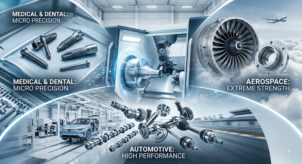
In reality, many advanced aerospace, automotive, and medical components cannot be produced by just one method. Some advanced 3D CAD models feature both complex milled contours and highly precise turned bearing surfaces.
In these scenarios, manufacturers combine these processes sequentially. The raw material may first be turned on a lathe to establish the high-tolerance outer diameters and smooth finishes, and then transferred to a 5-axis CNC mill to carve out complex, asymmetric internal cavities.
Start Your Project with CS Rapid MFG
Whether your project dictates the complex, multi-axis capabilities of CNC milling, or the high-speed, precision cylindrical production of CNC turning, CS Rapid MFG is equipped to handle it all.
As an ISO 9001:2015 certified manufacturer, our facility houses over 80 domestic and foreign high-precision CNC machines. We provide rapid prototypes and mass production parts across diverse materials—from Aluminum and Titanium to PEEK and POM. We are committed to shortening your pilot production cycles, offering parts in as fast as 5 days.
Don’t let manufacturing complexities slow you down. Contact CS Rapid MFG today or upload your 2D/3D files for an instant quote, and let our expert engineers provide a free DFM analysis to select the perfect machining process for your unique design.